
Introduction
An upcoming project requires a MIDI connection over USB. The product is simple: it’s a MIDI-controlled “thing” with some front-panel buttons and knobs and LED indicators as the user interface. The buttons and knobs control device parameters with status reflected by the LEDs. If a host computer is connected to the device over USB, then that computer can control it with a “virtual” front panel, and also changes made on the real panel are sent to the computer so the device and the computer can remain synchronized.
USB has supported MIDI devices, as a part of the USB Audio Device Class, since 1999, and the three major operating systems have built-in drivers for them. MIDI itself has been around even longer. Both specifications are mature, well-understood and well-supported.
An embedded microcontroller can be used to manage the USB interface and the other digital stuff. At first glance, implementing USB MIDI on a micro seems straightforward. After all, there is USB MIDI support for Arduino, and there’s a project for the STMF32 parts, and of course there’s the LUFA library which targets various Atmel parts.
For various reasons, I prefer Silicon Labs micros. While none of SiLabs’ USB micros (both 8-bit 8051 and 32-bit ARM) support High Speed, that is fine, as the USB MIDI class was specified for Full Speed. SiLabs provides an Eclipse-based IDE called Simplicity Studio which works as well as can be expected. The Keil C51 compiler tools are used for building C8051 and EFM8 projects (and the gcc compiler is used for the EFM32 ARMs) and C2-based programming and debug is built in. Finally, SiLabs provides a decent USB stack to handle most of the details of the USB interface.
The SiLabs USB stack doesn’t have support for the MIDI device class. And they don’t have an example of how to use the stack with devices that use Bulk transfers. OK, no problem, it’s time to write some code!
The USB MIDI device described here has two functions. One, it implements a USB-to-serial-MIDI dongle like the various M-Audio things, so it will use a UART to drive and receive messages over the standard MIDI DIN connector interface. Two, it allows the host to control “features” of a device, in this case an RGB LED, as well as allowing the device to send user-interface control changes (buttons, knobs) back to the host.
It will run on the SiLabs EFM8UB2 STK. Since MIDI requires an optoisolated receiver, a simple board must be built to support that. A schematic is shown later.
I will assume that the reader is familiar with the MIDI Specification, both at the physical layer and the protocol layer, so I won’t rehash any of that. I will point out where USB-MIDI and the standard MIDI overlap and where the former extends the latter.
USB-MIDI Device Class Basics
Note to the reader: it is helpful to have the USB MIDI and the USB Audio Class specs available. The USB MIDI class is a subclass of sorts under the Audio Class umbrella. The device descriptor requires an Audio Control Interface. For the actual MIDI data, the device must include one or more MIDI Streaming interfaces instead of an Audio Streaming interface. (The device can include one or more Audio Streaming interfaces if desired and if the converter hardware is available.)
The topology of a USB MIDI device function is described with a few different blocks and the connections between them. It must have a USB-MIDI Converter, and one or more Jacks are used to describe the source or sink of a MIDI data stream within the device. Elements are used to describe engines that convert MIDI data to audio or the converse. For purposes of this example, we do not use Elements. (This might change.) Also, the USB MIDI device class supports “Transfer Endpoints,” which are used to exchange data between the host and any defined Elements, and again for this example we do not use them.
There are two types of Jacks: Embedded and External. The easiest way to think of these two types is that Embedded Jacks describe connections where the MIDI data stay within the device, and External Jacks describe physical connections such as the standard DIN jack driven by a 31.25 kbps asynchronous serial transmitter. I believe that the proper use of Elements would be to have them be the source and sink for data going over Embedded Jacks, and a future revision of this code might take advantage of that. For now, I use External Jacks to describe how buttons are read and LEDs are set.
USB-MIDI “Cables”
Full-Speed MIDI has a wire rate of 12 Mbps, which is significantly faster than the MIDI UART’s rate of 31.25 kbps. This allows for one of the USB MIDI Class’s more interesting features, which is multiplexing multiple MIDI streams. This is done using virtual “ports” which are called “cables” in the USB MIDI spec. Up to sixteen “cables” can be muxed onto one USB Endpoint. It is as if each device had 16 MIDI Out ports and 16 MIDI In ports, of course without the nest of wires. And with the standard sixteen channels per virtual “cable,” a lot of MIDI messages can be sent and received on one USB cable.
MIDI Device Class Descriptors
The internet has very few examples of MIDI Device class descriptors. The aforementioned LUFA code has a generic descriptor, but it’s not clear what’s going on with it. I have a couple of USB-MIDI devices and a bus analyzer, so I was able to dump the descriptors for them to see what mine might look like. And between those dumps and the USB-MIDI spec, I came up with descriptors which work with the device design I described above. I apologize for including the Silicon Labs macros which are used to determine memory space. The descriptors are in a file conveniently called descriptors.c in the source code.
First we have the mandatory device descriptor:
SI_SEGMENT_VARIABLE(deviceDesc[],
	const USB_DeviceDescriptor_TypeDef,
	SI_SEG_CODE) =
{
	USB_DEVICE_DESCSIZE,            // bLength
	USB_DEVICE_DESCRIPTOR,		// bDescriptorType
	htole16(0x0200),		// bcdUSB
	0,				// bDeviceClass
	0,				// bDeviceSubClass
	0,				// bDeviceProtocol
	64,				// bMaxPacketSize
	USB_VENDOR_ID,			// idVendor
	USB_PRODUCT_ID,			// idProduct
	htole16(0x0100),		// bcdDevice
	1,				// iManufacturer
	2,				// iProduct
	3,				// iSerialNumber
	1,				// bNumConfigurations
};
The various constants must be defined somewhere, and in this case the first two are in the library source efm8_usb.h, as they are standardized and do not vary from design to design. The last two are design-dependent, and are in descriptors.h which is intended to be changed by the user.
The entries for bDeviceClass and bDeviceSubclass are zero, which indicates that the device is defined at the Interface level (which is pretty standard).
Next is the Configuration Descriptor. This is what tells the host about the device, and it tells how many Interfaces are included. Each Interface has both Standard and Class-specific descriptors.
In this design, there are two interfaces. One is the mandatory (for an Audio Class device) Audio Control interface, which tells the host that it’s an Audio Class device. This interface has two descriptors, the mandatory Standard Interface Descriptor and a Class-Specific Interface Descriptor. The second interface is the MIDI Streaming interface, which describes how the device handles data. This second interface has a mandatory Standard Interface Descriptor, and a Class-Specific Interface descriptor. A large part of the CSIF descriptor are the eight Jack descriptors, which tells the host about the device’s MIDI data routing. Finally, because the MIDI streaming interface presents MIDI In and MIDI Out data paths, there are two Endpoints for them. Each Endpoint has a Standard Endpoint descriptor and a Class-Specific Endpoint Descriptor.
/*
 * This is the Configuration Descriptor.
 */
SI_SEGMENT_VARIABLE(configDesc[],
    const USB_ConfigDesc_t,
    SI_SEG_CODE) =
{
// Configuration Descriptor header
	USB_CONFIG_DESCSIZE,		// bLength
	USB_CONFIG_DESCRIPTOR,		// bDescriptorType
	htole16(0x0085),		// wTotalLength, 133 bytes
	2,				// bNumInterfaces
	1,				// bConfigurationValue
	4,				// iConfiguration
	CONFIG_DESC_BM_RESERVED_D7,     // bmAttributes
	CONFIG_DESC_MAXPOWER_mA(100),   // bMaxPower
// Standard Interface Descriptor for Audio Control Interface
	USB_INTERFACE_DESCSIZE,		// bLength
	USB_INTERFACE_DESCRIPTOR,	// bDescriptorType
	0,				// bInterfaceNumber
	0,				// bAlternateSetting
	0,				// bNumEndpoints, this
                                        // uses the control endpoint
	USB_CLASS_AUDIO,		// bInterfaceClass
	USB_AUDIO_AUDIOCONTROL,		// bInterfaceSubClass
	0,				// bInterfaceProtocol
	5,				// iInterface
// Class-Specific Audio Control Interface Descriptor
	sizeof(USB_MIDI_CS_AC_IF_Descriptor_t),	// bLength
	USB_CS_INTERFACE_DESCRIPTOR,	// bDescriptorType
	MIDI_CS_IF_HEADER,		// bDescriptorSubtype
	htole16(0x0100),		// bcdADC
	htole16(0x0009),		// wTotalLength
	1,				// bInCollection
	1, 				// baInterfaceNr
// Standard Interface Descriptor for MIDI Streaming Interface
	USB_INTERFACE_DESCSIZE,		// bLength
	USB_INTERFACE_DESCRIPTOR,	// bDescriptorType
	1,				// bInterfaceNumber
	0,				// bAlternateSetting
	2,				// bNumEndpoints
	USB_CLASS_AUDIO,		// bInterfaceClass
	USB_AUDIO_MIDISTREAMING,	// bInterfaceSubClass
	0,				// bInterfaceProtocol
	6,				// iInterface
// Class-Specific Interface Descriptor for MIDI Streaming Interface
	sizeof(USB_MIDI_CS_MS_IF_Descriptor_t),	// bLength
	USB_CS_INTERFACE_DESCRIPTOR,	// bDescriptorType
	MIDI_CS_IF_HEADER,		// bDescriptorSubtype
	htole16(0x0100),		// BcdADC
	htole16(0x0061),		// wTotalLength
// Class-Specific Interface Descriptor for MIDI Jack 1.
// This jack is the sink for data from the USB host and intended for
// the "onboard" "port," which controls the RGB LED.
// This should appear as Outport MIDI Port 1 to the host computer.
// It connects to the USB OUT Endpoint 1.
	sizeof(USB_MIDI_In_Jack_Descriptor_t),	// bLength
	USB_CS_INTERFACE_DESCRIPTOR,	// bDescriptorType
	MIDI_CS_IF_IN_JACK,		// bDescriptorSubtype
	MIDI_JACKTYPE_Embedded,		// bJackType
	JACK1_EMBIN,		        // bJackID
        0, // Jack index of a string descriptor describing this jack
// Class-Specific Interface Descriptor for MIDI Jack 2.
// This jack is the source of MIDI packets intended to be used by the
// "onboard" "port" which controls the RGB LED. It connects to one
// source, which is Jack 1.
// It is an "External" type because it connects to stuff outside of
// the USB MIDI function. Can this be embedded?
	USB_MIDI_OUT_JACK_DESCRIPTOR_SIZE(1),	// bLength
	USB_CS_INTERFACE_DESCRIPTOR,		// bDescriptorType
	MIDI_CS_IF_OUT_JACK,			// bDescriptorSubtype
	MIDI_JACKTYPE_External,			// bJackType
	JACK2_EXTOUT,				// bJackID
	1,					// bNrInputPins
	JACK1_EMBIN,				// baSourceID
        1,					// baSourcePin
	0,					// iJack
// Class-Specific Interface Descriptor for MIDI Jack 3.
// This jack is an input to the USB MIDI function, and it gets its
// data from the changes to the buttons and joystick.
	sizeof(USB_MIDI_In_Jack_Descriptor_t),	// bLength
	USB_CS_INTERFACE_DESCRIPTOR,		// bDescriptorType
	MIDI_CS_IF_IN_JACK,			// bDescriptorSubtype
	MIDI_JACKTYPE_External,			// bJackType
	JACK3_EXTIN,				// bJackID
	0,					// iJack
// Class-Specific Interface Descriptor for MIDI Jack 4.
// This jack is an output from the USB MIDI function, and it feeds the
// USB In Endpoint. It gets its data from Jack 3, that is, the buttons
// and joystick.
// This should appear as MIDI INPUT Port 1 to the host computer.
	USB_MIDI_OUT_JACK_DESCRIPTOR_SIZE(1),	// bLength
	USB_CS_INTERFACE_DESCRIPTOR,		// bDescriptorType
	MIDI_CS_IF_OUT_JACK,			// bDescriptorSubtype
	MIDI_JACKTYPE_Embedded,			// bJackType
	JACK4_EMBOUT,				// bJackID
	1,					// bNrInputPins
	JACK3_EXTIN,				// baSourceID
	1,					// baSourcePin
	0,					// iJack
// Class-Specific Interface Descriptor for MIDI Jack 5.
// This is the source of the MIDI data packets intended for the serial
// MIDI OUT port. It should appear as MIDI OUTPUT Port 2 to the host.
// It connects to the USB OUT 1 Endpoint.
	sizeof(USB_MIDI_In_Jack_Descriptor_t),	// bLength
	USB_CS_INTERFACE_DESCRIPTOR,		// bDescriptorType
	MIDI_CS_IF_IN_JACK,			// bDescriptorSubtype
	MIDI_JACKTYPE_Embedded,			// bJackType
	JACK5_EMBIN,				// bJackID
	0,					// iJack
// Class-Specific Interface Descriptor for MIDI Jack 6
// This is the sink for the MIDI data packets intended for the serial
// MIDI OUT port. It gets its data from Jack 5.
	USB_MIDI_OUT_JACK_DESCRIPTOR_SIZE(1),	// bLength
	USB_CS_INTERFACE_DESCRIPTOR,		// bDescriptorType
	MIDI_CS_IF_OUT_JACK,			// bDescriptorSubtype
	MIDI_JACKTYPE_External,			// bJackType
	JACK6_EXTOUT,				// bJackID
	1,					// bNrInputPins
	JACK5_EMBIN,				// baSourceID
	1,					// baSourcePin
	0, 					// iJack
// Class-Specific Interface Descriptor for MIDI Jack 7
// This is the sink for data coming from the serial MIDI IN port, to
// go back to the host computer.
	sizeof(USB_MIDI_In_Jack_Descriptor_t),	// bLength
	USB_CS_INTERFACE_DESCRIPTOR,		// bDescriptorType
	MIDI_CS_IF_IN_JACK,			// bDescriptorSubtype
	MIDI_JACKTYPE_External,			// bJackType
	JACK7_EXTIN,				// bJackID
	0,					// iJack
// Class-Specific Interface Descriptor for MIDI Jack 8
// This is the source of the data for the USB IN Endpoint. It gets its
// data from Jack 7, which is fed by the DIN MIDI IN Port.
// This connects to USB IN Endpoint 1.
	USB_MIDI_OUT_JACK_DESCRIPTOR_SIZE(1),	// bLength
	USB_CS_INTERFACE_DESCRIPTOR,		// bDescriptorType
	MIDI_CS_IF_OUT_JACK,			// bDescriptorSubtype
	MIDI_JACKTYPE_Embedded,			// bJackType
	JACK8_EMBOUT,				// bJackID
	1,					// bNrInputPins
	JACK7_EXTIN,				// baSourceID
	1,					// baSourcePin
	0,					// iJack
// Standard Endpoint Descriptor for Bulk In Endpoint 1
	USB_ENDPOINT_DESCSIZE,			// bLength
	USB_ENDPOINT_DESCRIPTOR,		// bDescriptorType
	0x81,					// bEndpointAddress
	USB_EPTYPE_BULK,			// bmAttributes
	htole16(SLAB_USB_EP1IN_MAX_PACKET_SIZE),// wMaxPacketSize
	0,					// bInterval
// Class-specific Endpoint Descriptor for Bulk In Endpoint 1
	USB_MIDI_CS_STREAMING_BULK_ENDPOINT_SIZE(2),	// bLength
	USB_CS_ENDPOINT_DESCRIPTOR,		// bDescriptorType
	USB_MIDI_CS_EP_MS_GENERAL,		// bDescriptorSubtype
	2,					// bNumEmbMIDIJack
	JACK4_EMBOUT, JACK8_EMBOUT, 		// baAssocJackID
// Standard Endpoint Descriptor for Bulk Out Endpoint 1
	USB_ENDPOINT_DESCSIZE,		// bLength
	USB_ENDPOINT_DESCRIPTOR,	// bDescriptorType
	0x01,				// bEndpointAddress
	USB_EPTYPE_BULK,		// bmAttributes
	htole16(SLAB_USB_EP1OUT_MAX_PACKET_SIZE),// wMaxPacketSize
	0,				// bInterval
// Class-specific Endpoint Descriptor for Bulk Out Endpoint 1
	USB_MIDI_CS_STREAMING_BULK_ENDPOINT_SIZE(2),	// bLength
	USB_CS_ENDPOINT_DESCRIPTOR, 	// bDescriptorType
	USB_MIDI_CS_EP_MS_GENERAL,	// bDescriptorSubtype
	2,				// bNumEmbMIDIJack
	JACK1_EMBIN, JACK5_EMBIN	// baAssocJackID
};
USB-MIDI “Jacks”
The relationship between the Jacks, and between the Jacks and the Endpoints is likely the most confusing aspect of this. Remember that the Jacks describe the inputs to and the outputs from the USB-MIDI function. And what might seem even more confusing is that more than one Jack can be associated with a particular part of the function. So let’s look at this in more detail.
Recall that this example design has four MIDI ports. Two are the standard serial ports (wired MIDI In and Out on DIN connectors) and the other two are a virtual “Out” port that lets the host control stuff (the RGB LED in this example design) and a virtual “In” port that sends button-press data back to the host. This means there are four data “paths” and we need eight Jacks — four In, four Out — to describe this routing, and the descriptors above show them. Pay attention to the Class-Specific Endpoint Descriptors, as they specify how data are routed to or from the Endpoint from or to the Jacks, and note that the endpoints each feed two Jacks.
- Data path from host computer to control RGB LED:
OUT Endpoint 1 -> Jack 1 -> Jack 2 -> LED
- Data path from joystick and button handler to host computer:
Button handler -> Jack 3 -> Jack 4 -> IN Endpoint 1
- Data path from host computer to DIN MIDI OUT port:
OUT Endpoint 1 -> Jack 5 -> Jack 6 -> serial transmitter/MIDI OUT DIN port
- Data path from DIN MIDI IN port to host computer:
Serial receiver/MIDI IN DIN port -> Jack 7 -> Jack 8 -> IN Endpoint 1
But … what about “Cables?”
Indeed, what about cables? The descriptors say nothing about them at all! It seems obvious that with one OUT Endpoint, we connect to the MIDI OUT DIN connector and the LED on different cables, and also the buttons/joystick connect to the one IN Endpoint on a different cable from the MIDI In DIN connector. Thus the USB OUT Endpoint connects to two cables and the USB IN Endpoint connects to two cables. (That’s why the Jacks are specified in the Class-Specific Endpoint Descriptors.)
All the descriptors do is to tell the host computer about the topology of the MIDI “network,” if you will, associated with the device. They don’t indicate how that topology is actually implemented. That’s up to the firmware. But how does the firmware know how to actually do all of this routing that the device told the host it can do? Well, first, we must introduce the USB-MIDI Event Packet (MEP).
The USB-MIDI Event Packet
Readers familiar with standard serial MIDI know that MIDI Messages are sent in packets of one, two or three bytes for non-SysEx messages, and SysEx messages can have any number of bytes between the SOX and EOX status bytes. USB-MIDI standardizes on a four-byte MIDI Event Packet, shown here:
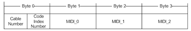
Byte 0 is the packet header. Its upper nybble is the four-bit Cable Number. This tells the device which cable the packet came from (in case of USB IN Endpoints) or which cable is the destination for the packet (for USB OUT Endpoints). The lower nybble of the header is the Code Index Number, which indicates how the remaining three bytes of the packet should be interpreted. For most of the packets, the three payload bytes are a standard MIDI message, so the CIN can appear to be redundant. But this is also how multibyte SysEx messages can be broken up into three-byte chunks to fit into the USB-MIDI Event Packet.
MIDI Event Packets on the USB and this example design
For USB OUT Endpoint MIDI transactions: the host will fill its USB OUT packets with one or more MEPs, up to the Endpoint’s maximum packet size, based on the MIDI traffic generated by applications. The USB packet ends up in the device micro’s Endpoint buffers in a device-specific manner. At some point, the micro’s USB interrupt is asserted and parsed and now we have our Event Packets sitting in a buffer, waiting to be handled. The handler itself is in the main() function in EFM8-USB-MIDI_main.c.
The micro firmware should pop an MEP from the buffer and inspect its header. The Cable Number and the Code Index Number tell the micro how to handle the packet. In the case of our simple example, Cable Number 0 is the “virtual” device where the USB OUT controls the RGB LED. Cable Number 1 goes to the serial MIDI Out port. (My unproven assumption is that since the Class-Specific Endpoint Descriptor tells the host how many “Ports” or cables the device has, the host won’t do something silly like send a packet to a non-existent Cable Number.)
Packets intended for the hardware serial port have the CIN parsed and a standard MIDI message packet is built from the MEP. That packet is then sent to the serial transmitter’s holding FIFO.
For packets intended for the “virtual” port, which controls the RGB LED, the first payload byte is inspected. We use MIDI Control Change messages to set the brightnesses of the three colors. The message indicates which control (in byte 2 of the Event Packet) and also the control’s value (in byte 3). If the control matches one of the four we expect (I chose GP Control 5, 6, 7 and 8), the value is used to set the LED color and intensity. Other controls are simply ignored.
For USB In Endpoint MIDI Transactions: This is where the micro takes either events on the buttons and joystick, or messages from the serial MIDI IN connection, and builds MIDI Event Packets and sends them back to the host.
For the former, periodically the micro polls the state of the joystick and buttons and builds a report with the state of those controls. Then a parser in main() tests the state of each control, and if toggled, a MEP is built for a Control Change message with the appropriate state, and that packet is written to the micro’s USB device endpoint FIFO to be sent off to the host.
For the latter, MIDI messages coming from the serial MIDI In must be parsed and one or more proper MEPs built. The parsing is done by a state machine in the file midi_uart.c in the function MIDIUART_readMessage(). This parsing is rather more complex than one might expect, as a message might not be fully received when that function is called. Also it needs to handle MIDI running status and the varying sizes of SysEx messages. In any case, the function builds MEPs on the fly and when one is completed, the function returns the MEP in a point argument and returns true, and the main() function will then just write the entire MEP to the Endpoint buffer.
The EFM8UB2 and the Silicon Labs EFM8 USB stack
There is some discussion of how to use this stack over at the SiLabs 8-bit MCU forum, and I had some back and forth with SiLabs tech support to get to the bottom of how the part works. It turns out that there are some important details left out of the part documentation.
The code uses the efm8_usb library. The basic idea, after getting the descriptors correct and having it actually enumerate on the USB, is that you access the stack through two API functions, USBD_Write() and USBD_Read(), and you get access to read data (from a USB OUT transaction) using the transfer-complete callback USBD_XferCompleteCb().
USBD_Write()
The USBD_Write(), to write data to the host for a USB IN transaction, is relatively straightforward. You just pass to that function a pointer to a buffer containing the data to send, the size of that buffer and the Endpoint number, and off it goes. You can also indicate whether you want a callback after the transaction is complete, but for this case none is needed. I did find it to be necessary to ensure that the endpoint was not busy before calling USBD_Write(). Examples of this are in my main() function in EFM8-USB-MIDI_main.c.
USBD_Read()
The USBD_Read() is not as simple, and the lack of documentation about how it is supposed to work doesn’t help. (This is why my question on the forum was “when are you supposed to call this function?”) Despite its name, this function doesn’t return a buffer full of data from the last USB OUT transaction. Rather, it hands a buffer over to the stack and then the stack indicates internally that it is ready to handle USB OUT transactions. It “primes the pump,” so to speak. But this still doesn’t answer my question, so let’s do that now.
First, enable the USBD_DeviceStateChangeCb() callback. This will get called after the device has successfully enumerated on the USB, and the stack sets the device state to “configured.” This means that the device is now on the bus and ready for action. The host may now start sending USB MIDI packets to the device. First, create a global variable that is the size (in bytes) of the OUT Endpoint’s maximum packet size. (Realize that the Endpoint packet is not the same as the MIDI Event Packet!)
SI_SEGMENT_VARIABLE(
    EndpointBuffer[SLAB_USB_EP1OUT_MAX_PACKET_SIZE],
    uint8_t,
    SI_SEG_IDATA);
I put this line in the source file callback.c, the same file which contains the callbacks described above. (The file is generated by Simplicity Studio’s configurator, but thankfully it is not overwritten by later configuration changes.) Since we use this global variable in other places, you must extern it wherever else you use it (or put it in a header with the extern decoration).
In this callback, then, we do the initial call to USBD_Read():
void USBD_DeviceStateChangeCb(USBD_State_TypeDef oldState,
                              USBD_State_TypeDef newState) {
	UNREFERENCED_ARGUMENT(oldState);
	if (newState == USBD_STATE_CONFIGURED) {
		USBD_Read(EP1OUT,
			&EndpointBuffer,
			SLAB_USB_EP1OUT_MAX_PACKET_SIZE,
			true);  // Call XferCompleteCb when buffer full.
	}
} // USBD_DeviceStateChangeCb()
And now the device is ready to handle the first USB transaction on Endpoint Out 1. Note that we have set the “use callback” argument to TRUE.
In the endpoint interrupt handler (part of the efm8_usb stack) the first thing that happens is that the number of bytes in the Endpoint FIFO is fetched. Then that number of bytes is popped from that FIFO and stored in our Endpoint buffer (passed in the call to USBD_Read()). At that point, we have one or more MIDI Event Packets sitting in our buffer, waiting to be handled, and this is when the transfer-complete callback is invoked.
uint16_t USBD_XferCompleteCb(uint8_t epAddr, USB_Status_TypeDef status,
		uint16_t xferred, uint16_t remaining) {

	USBMIDI_Message_t xdata mep;
	uint8_t *epb;

	UNREFERENCED_ARGUMENT(remaining);

	if ((epAddr == EP1OUT) && (status == USB_STATUS_OK))
	{
		epb = EndpointBuffer;
		while (xferred) {
			mep.header = *epb++;
			mep.byte1 = *epb++;
			mep.byte2 = *epb++;
			mep.byte3 = *epb++;
			USBMIDIFIFO_Push(&mep);
			xferred -= 4;
		}
	}

	// always return zero for bulk endpoints.
	return 0;
} // XferCompleteCb
In the callback we make sure we’re handling EP1OUT’s event. Then we build one or more MIDI Event Packets and push them onto a FIFO for later parsing. There’s a big assumption here, which is that the number of bytes transferred to our Endpoint buffer in the ISR is a multiple of the size of the MIDI Event Packet (four bytes). It might be a good idea to always check for that to be true, and then figure out how to handle it, lest we go off into the weeds with the buffer pointer.
Back in the main program loop, the call to USBMIDIFIFO_Pop (&usbmep) checks to see if the FIFO written by the callback actually has anything in it, and if so, one Event Packet at a time is popped and parsed.
So, really, when do we call USBD_Read()?
And the above still does not answer the question, “… so when do we call USBD_Read()?” I’m afraid that the answer is rather implementation-dependent and it also involves a detail of how the EFM8UB2’s USB serial-interface engine.
In most cases, a device is able to handle each USB OUT transaction’s input (to the micro) data in a timely manner, that is, before the next packet comes in. That is partially the case here, as MIDI Event Packets for the “virtual” Cable (which lights the RGB LED) is handled immediately and there’s no concern about not being ready for the next packet. So in that case, we can call USBD_Read() again immediately after we’ve parsed a packet.
But our example device has a complication: one of its functions is as a “USB to MIDI converter” dongle, so all MIDI Event Packets on the “real” Cable are just handed off to the UART that implements the serial transmitter for the DIN connector. And the rub is that the UART at 31.25 kbps is much much slower than Full Speed USB, and if you’re sending packets from a computer over USB, you can eventually overflow any FIFO you can put in front of your serial transmitter.
USB does offer the correct way for a device to throttle the bus in this sort of circumstance. Generally, in response to a transfer from the host, the device will send an ACKnowledge packet back. This lets the host know it can send more data. However, if the device is temporarily unable to deal with new data, it should respond by sending a No Acknowledge (NAK) packet back to the host. The host will see that, and at some point later it will retry sending the previous packet that the device was unable to handle. If the device NAKs again, the host will retry again, and keep doing so until the device finally accepts the packet.
I challenge you to read through the EFM8UB Reference Manual and tell me where it says how you are supposed to have the device NAK a transaction. Spoiler: you won’t find it. But SiLabs tech support was helpful in this, and there’s a simple and effective answer.
For each enabled Endpoint (IN or OUT) in the design, the EFM8UB2 has a FIFO. For USB OUT transactions, the deserialized data bytes are written to that FIFO. When the transactions are complete, the USB interface engine automatically sends the ACK response and then it interrupts the processor, which then figures out what to do.
But, for the OUT transactions, that interrupt is asserted only if a call to USBD_Read() was made. The interface continues to ACK each transaction. If no call, then the FIFO continues to fill as packets are received. And at some point, that FIFO is full. And when the FIFO is full, the USB interface will no longer ACK transactions, but rather it NAKs them.
Therefore, the USB interface was designed to do exactly what is required in the case when the device is not ready to deal with new data. It’s just not documented.
When the device is ready to deal with new data, all it needs to do is call USBD_Read() and then the USB interrupt will be immediately re-enabled, which means the ISR will get called right away and the oldest data in the FIFO will be transferred to the user buffer. And as the Endpoint FIFO empties, the host is re-trying the packet that was NAKed and eventually it will be ACKed and accepted. So no data packets are lost. (I should point out that this applies only to Bulk and Interrupt transactions, and not to Isochronous transactions, which are never NAKed and anyway cannot be retried.)
Back to our example, which is where we want to transmit received MIDI Event Packets out over the much slower serial port. In this case, those packets are re-formatted for the serial MIDI format and the packets are written to a FIFO that’s in front of the serial transmitter. If that FIFO gets full, obviously it cannot accept more packets. So after receiving an MEP and dealing with it (remember it might be for the internal “virtual” port), we see if there’s room for more in serial packet FIFO, and if so, then we’ll call USBD_Read() again. If there is no room in the FIFO, then we don’t, and let the serial transmitter pop bytes from it and eventually it has room again, and we can re-arm the endpoint and continue.
This example
The source code is available here (.zip). It was created using Simplicity Studio 4 and its Hardware Configurator, and as noted above it targets the EFM8UB2 STK, so as part of the design set-up it pulled in the various BSP features of interest (the joystick, the buttons, the RBG LED). I created directories called usb_audio, which has a couple of headers which define things, as well as the implementation of the USB-MIDI Event Packet FIFO. I also created a directory called midi, which also has useful defines. The most interesting stuff is in midi_uart.c. This is where you will find the code that implements the FIFOs in front of the micro’s UART1, and the MIDIUART_readMessage() function, which parses MIDI messages from the serial receiver and creates MIDI Event Packets.
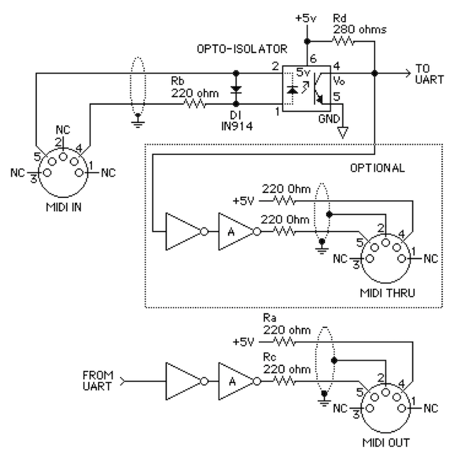
Unzip and import into your Simplicity Studio 4 workspace in the usual way. It should build for the EFM8UB20F64G-x-QFP48 without incident, and it can be loaded onto the STK directly. In order to use the old-style serial MIDI interface, you need to build up a little board that connects to the pins for UART1. A reasonable schematic is here (taken directly from the MIDI spec). A 6N138 optoisolator works well.
Some final comments. First and foremost, this is meant to show valid USB-MIDI Class descriptors and implement a USB-to-MIDI converter like the M-Audio Uno. It also shows how incoming (via USB Out) messages can be parsed and used to control something on a board, and it shows how to build messages from button presses to report user-interface changes back to the host.
It is not a synthesizer/sound-generator module, although there’s no reason why one cannot expand on this to do so. MIDI Note-On and Note-Off messages are easily parsed and used to do what their names imply. (Perhaps one could use the micro’s PWM and play different-frequency notes based on the Note-On and Note-Off messages.)
Also, it is not intended to be the be-all/end-all explanation of how USB-MIDI is supposed to work.
Thanks for this. I have some old C8051F340/F380 Keil projects I want to bring into the EFM8UB2 world and it’s been hell so far. This should be very helpful. To add insult to injury, I’ve also done one EFM8UB1 project and it’s substantially different too! Simplicity Studio is not an accurate name for their new “IDE” and framework.
The EFM8UB3 is also different from the other two.
And Simplicity Studio 5 has changed things again, and I haven’t gone back to check to see whether this code done in SS4 will work unchanged.
That said, I’ve found that the SiLabs USB stack is the easiest to extend to unsupported classes among the various microcontroller vendors. TI’s Tiva M4 is workable. NXP and Atmel/Microchip? Yikes, don’t even bother.
Why they can’t simply do what SiLabs does and have a callback invoked whenever any OUT endpoint receives a packet or any IN endpoint finishes sending a packet is beyond me.
Well, my project inexplicably completed itself. The F380 *is* a UB2. I don’t have to port my project(s), I can just order either part. I think my trip into the SILabs “framework” will have to wait for another project then. Maybe an EFM32, but I had been learning STM32 in my spare time.
I had not heard that the F380 was the same as the UB2 … but that doesn’t surprise me!
Every time I look at STM32 I see horror stories about the libraries and the awful documentation.